.svg)


![]()


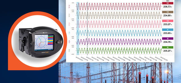
A Phasor Measurement Unit, or PMU for short, is the essential building block in the platform called Wide Area Monitoring System (WAMS).
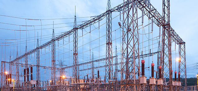
These systems were developed to provide an overall real-time health check of nation-wide transmission grids, predicting and helping to prevent power failures, analyzing those which did take place.
By interfacing Global Positioning System (GPS) receivers or clocks, or using Precision Time Protocol (PTP) the PMU reaches micro-second precision. This enables it to provide razor-sharp resolution snapshots of the angles formed by the measured parameters.
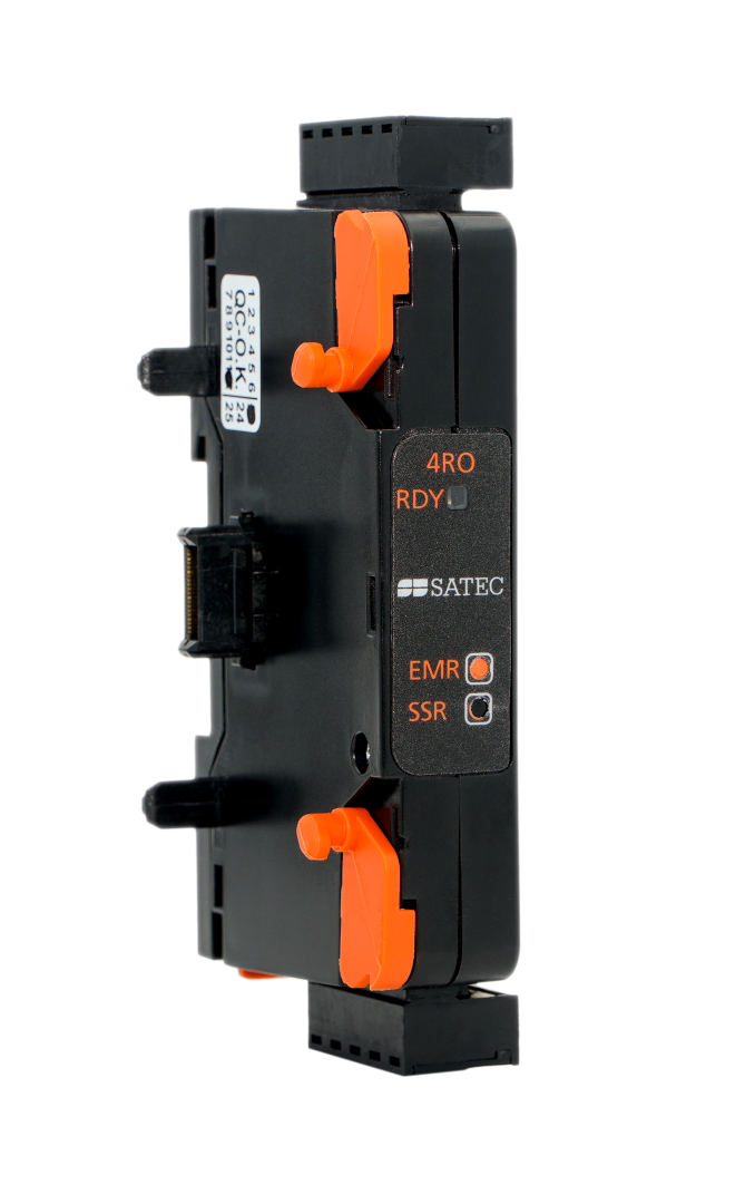
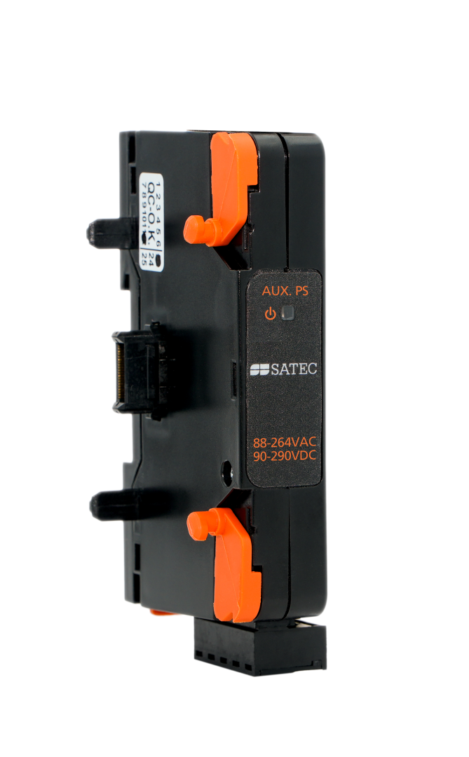
Providing the highest performance, and incomparably cost-effective, the PMU PRO is a true game-changer, especially in the field of Distribution System Operators (DSO). It communicates with 3rd party Phasor Data Concentrators (PDC), an important WAMS component in itself, enabling versatility.
 PMU PRO Technical Datasheet