>  Home >  Products >  PMU PRO

Phasor Measurement Unit

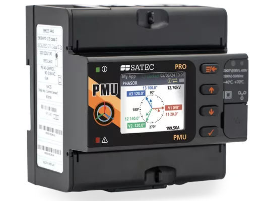
A Phasor Measurement Unit, or PMU for short, is the essential building block in the platform called Wide Area Monitoring System (WAMS).
These systems were developed to provide an overall real-time health check of nation-wide transmission grids, predicting and helping to prevent power failures, analyzing those which did take place.

Providing the highest performance, and incomparably cost-effective, the PMU PRO is a true game-changer, especially in the field of Distribution System Operators (DSO). It communicates with 3rd party Phasor Data Concentrators, an important WAMS component in itself, enabling versatility.

  • Full IEEE C37.118.1 / IEC 60255-118-1:2018 compliance for both:
    • M-Class
    • P-Class
  •  Dual Protocol
    • IEC 61850-9-2
    • IEEE C37.118.2
  • Versatile micro-second resolution time-sync:
    • PTP
    • IRIG-B
  • Up to 240 frames/sec
  • Super-compact design
  • Expected Steady State Total Vector Error (TVE)
    at nominal frequency < 0.05%

Phasor Measurement Unit

  • IEEE C37.118.1-2011, IEEE C37.118.1a-2014 and IEC/IEEE 60255-118-1:2018 P-Class and M-class performance compliance
  • IEEE C37.118.1 compliant three-phase voltage, current, and positive and negative sequence phasor measurements synchronized to a common UTC time reference
  • IEEE C37.118.1 synchronous frequency and Rate of Change of Frequency (ROCOF) measurements
  • Clock synchronization to a UTC time reference using an IRIG-B timecode source or an IEEE 1588 PTPv2 master clock source
  • IEEE C37.118.2 commanded client-server UDP and TCP data transmission and spontaneous UDP data transmission over IP protocol
  • IEEE C37.118.2 reporting rates from 1 to 200/240 frames/s
  • Streaming of phasor data over Ethernet using the IEC 61850-9-2 multicast sampled value (SV) service with IEEE C37.118.2 compliant mapping of synchrophasor data upon IEC 61850-9-2 and IEC 61850-90-5 guidelines
  • Expected steady-state total vector error (TVE)
    at nominal frequency: < 0.05%
  • Streaming rate: 1 to 200 or 240frames/s @ 50 or 60Hz, respectively
  • IEEE C37.118.2
    • Synchrophasor data frames transmit a time stamped set of measurements that include phasor estimates, frequency deviation from the nominal power line frequency or actual frequency, and the rate of change of frequency. In addition, the data frame can be expanded to contain analog data (total active, reactive and apparent power, and power factor) and digital input status information.
      Phasor components can include three voltage and three current phasors, positive sequence voltage and current phasors, negative sequence voltage and current phasors, or all of them in one frame.
      Complex phasor values can be sent in a rectangular coordinates format (real and imaginary) or in polar coordinates (magnitude and angle). Phasor and frequency data can be represented in 32-bit IEEE floating-point format or as 16-bit scaled integer numbers. When using the integer format, the data conversion factors are provided in IEEE C37.118.2 configuration frames.
    • Client-server UDP and TCP data transmission; spontaneous UDP data transmission over IP protocol
    • Optional IEEE C37.118.2 frame extensions with analog data (total active, reactive and apparent power and power factor) and digital status data (up to 32 inputs)
    • The PMU PRO supports CFG-1, CFG-2 and CFG-3 configuration frames.
      In spontaneous UDP data transmission mode, CFG-2 or CFG-3 configuration frames can be sent spontaneously without an explicit user command. When enabled, a configuration frame is sent periodically every 30 seconds.
  • 5 data streaming slots for continuous synchrophasor data streaming via unicast UDP or/and TCP connections

Logging, Recording & Programming

  • Programmable controller: up to 32 control setpoints and half-cycle scan time
  • OR, AND, arithmetical functions logic, extensive triggers, programmable thresholds and delays, relay control, event-driven data recording
  • Event recorder for logging internal diagnostic events, power faults and operations of the logic controller and digital I/O
  • Eight data recorders with programmable datasets for data logging on a periodic basis and on any internal or external trigger
  • 32 digital counters for counting internal events and pulses from external sources
  • 16 interval timers with programmable periods from half cycle to 24 hours for periodic recording and triggering timed operations

Variable Current Inputs

  • 5A
  • 1A

Voltage Measurement Inputs

  • Measurement category: CAT III
  • Operating range: up to 277/480 VAC +25%


I/O

Built-in I/O 

  • 1 AI (±1 mA; 0-1 mA; 0-20 mA; 4-20 mA)
  • 1 SSR (100mA/250V AC/DC)
    External power supply 24/48/125/250V DC
  • 1 DI
    Internally wetted @ 24VDC

4 Relay Outputs
Electromechanical (SPST Form A)

Available options:

  • 5A/30 VDC
  • 5A/250V AC
  • 100mA/800V DC

Combo: 4 Digital Inputs + 2 Relay Outputs

Available per above specifications

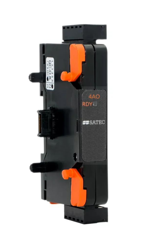
4 Analog Outputs

Universal (configurable) isolated analog outputs
(±1 mA; 0-1 mA; 0-20 mA; 4-20 mA)

Communication interfaces

  • Two 10/100Base-T IEEE 1588 Ethernet ports with packet forwarding/routing capabilities; connecting to Ethernet through one or two different network switches, or daisy chaining multiple devices to a switch using a linear or ring network topology (daisy chaining is not available for PTP-enabled devices); up to 8 simultaneous TCP connections via Modbus TCP, DNP3, IEC 60870-5-104, IEC 61850 (up to 5 client associations, GOOSE and MSV publishers) protocols
  • Up to 5 TCP or/and UDP synchrophasor data streams via C37.118.2 protocol
  • Full speed USB 2.0 type C port for local configuring and monitoring the device via Modbus RTU protocol
  • RS-485 serial communication port; 2400 to 115200 bps; Modbus RTU/ASCII, DNP3 and IEC 60870-5-101 protocols (the port is not operational if the IRIG-B time synchronization source is used)
  • Modbus TCP notification client
  • Expertpower client

Display

  • High contrast 1.77” TFT color graphics display with configurable backlight
  • Multi-page displays; time, instrumentation and service data
  • Menu-driven setups
  • Multilanguage support

Real-Time Clock & Synchronization

  • High-accuracy real-time clock with a lithium backup battery
  • Clock synchronization to a UTC time reference using an IRIG-B timecode source or an IEEE 1588 PTPv2 master clock
  • Daylight saving time shift for local time indication with configurable DST start and end time

Power Supply

Built-in: 57.7-277V AC / 48-290V DC

Additional options:
  • AUX 88-264V AC / 90-290V DC
  • AUX 9-36V DC

Enhanced Meter Security

  • 3 levels Password security for protecting meter setups and accumulated data from unauthorized changes

Mounting

  • DIN Rail mount


Modules

img

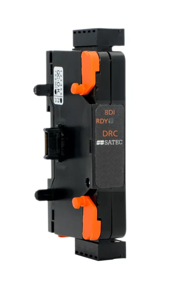
8 DI

8 optically isolated digital inputs, available as:
  • 24V dry contact
  • 24/48/125/250V AC/DC wet input

programmable de-bounce time from 1 ms to 1 sec
1ms sampling rate
1pps time synchronization

img

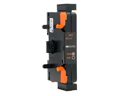
4 DO

4 optically isolated digital outputs, available as:
  • Electro-Mechanical relay, 250V / 5A AC
  • Solid-State Relay, 250V / 0.1A AC

img

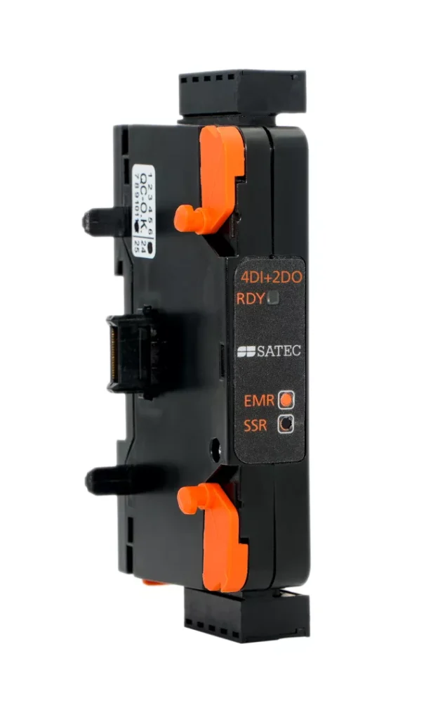
Combo: 4 DI + 2 RO

Available per above specifications (DI: @ 24V DC only)
img

4 Analog Outputs

Universal (configurable) isolated analog outputs
(±1 mA; 0-1 mA; 0-20 mA; 4-20 mA)
img

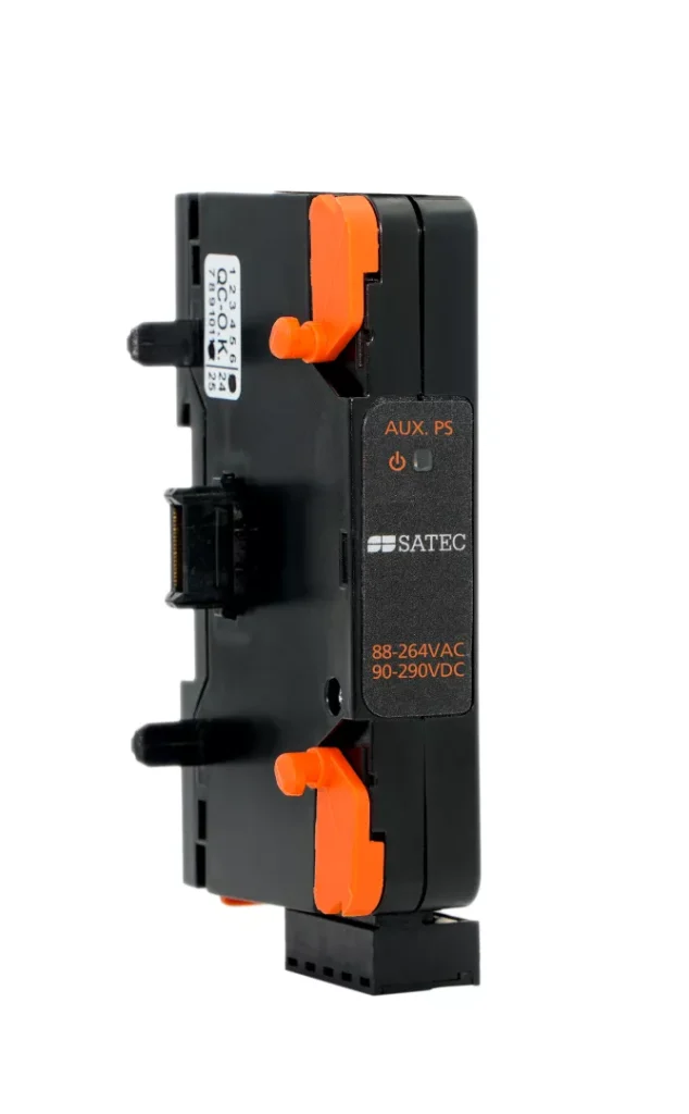
Auxiliary Power Supply

  • 88-264V AC
  • 90-290V DC

img

DC Auxiliary Power Supply

24V DC (9-36V DC)

img

Portable EDL180 Analyzer

img

PM180 DFR: Zero-Outage retrofit

img

Phasor Measurement Unit

img

PM180-RDM180

Contact now

one of our experts


    Featured Content

    top